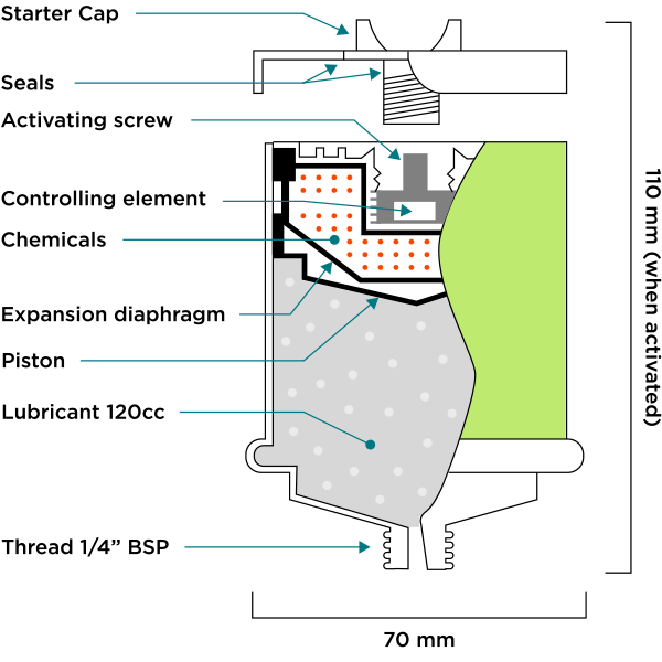
The starter caps are color coded. Ensure that the color of the starter cap matches the color of the activator screw in the base of the GreaseMax®, into which the starter cap will be screwed.
- Screw the starter cap in hand tight. (While the starter cap is being turned down, the seals will be heard to break.
- Then use a screw driver or similar to tighten the cap FIRMLY. This is essential to ensure a gas and liquid tight seal.
Do not loosen the starter cap or attempt to remove it.
When this has occurred GreaseMax® is operational. Allow the following minimum starting times: 1 month units – 8 hours, 3 month units – 24 hours, 6 month units – 30 hours, 12 month units – 40 hours, for lubricant discharge to commence. (see “Operation of GreaseMax®“).
Pre–grease with a grease gun before the first installation. The short time delay will not adversely affect bearings which have been properly pre–greased before the installation of GreaseMax®. For subsequent installations, pre–greasing is not necessary as prior use of GreaseMax® will have ensured that there is adequate grease in the bearings.
Pre-greasing before the first installation of GreaseMax® is also important to ensure that all grease ways are free of old hard grease which can block completely the grease ways.
GreaseMax® is designed to operate in most conditions. It will operate satisfactorily in:
- Areas of vibration. If this includes high shock loading, consider using mounting brackets and/or remote mounting with flexible feed lines.
- Underwater, wet or humid installations.
- Heat and cold (see discharge table below for discharge rate variations)
GreaseMax® units may be mounted in any position. Movement is OK but brackets may be required to support the unit. For oil filled units see section 4.5
4.1 GreaseMax® discharge rates
GreaseMax® is designed to operate at an average temperature of 770F. The discharge rate and operating period of GreaseMax® will be different if the average operating temperature varies from 770F. The following table gives details.
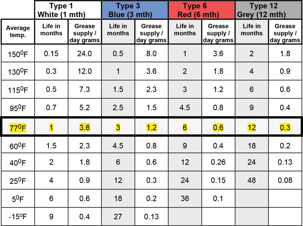
Note: The average temperature is the average operational temperature of the GreaseMax® unit. This may be different to the average environmental temperature.
4.2 Output pressure of GreaseMax
GreaseMax® develops sufficient pressure for most applications including use on feed lines. The pressure required to move grease into a rotating bearing, with the grease nipple removed, is normally not high. GreaseMax® holds the output pressure virtually in equilibrium with grease-way resistance.
4.3 Effect of bearing and grease way pressure
GreaseMax® builds up discharge pressure to the point where fundamentally a balance exists between the resistance of the grease way and the output pressure of the GreaseMax®. For example, if GreaseMax® is activated and allowed to discharge without being placed on a bearing, the full operating period will be taken before the unit is empty. If GreaseMax® is activated and placed on a grease-way requiring pressure GreaseMax® will build up to this pressure and then discharge according to its normal operating period. GreaseMax® adjusts to grease way resistance but does not rely on this resistance to control its’ operation.
GreaseMax® will maintain the pressure balance. If something occurs to change the grease way resistance, then GreaseMax® will automatically adjust its discharge pressure to accommodate this change.
4.4 Installation with extension lines
GreaseMax® may be used with extension lines for remote positioning. Extension lines are also useful for installations where extreme movement or shock loadings may be applied to the GreaseMax®. In this case, mount the GreaseMax® firmly in a bracket (which DIS can supply) and feed the lubricant into the bearing via tubing.
| Lubricant | Maximum line length* | Min. INSIDE diameter |
| Grease | 1.6 yards | 8mm |
| Oil | 10 yards | 3mm |
*Note: It is possible to install GreaseMax on longer feed lines than the above. For proposed installations outside these limits call for specialist advice.
All extension lines MUST be pre–filled with lubricant. We recommend only clear extension lines, so that the condition of the lubricant can always be observed.